Fitting an Inverter Charger Guide
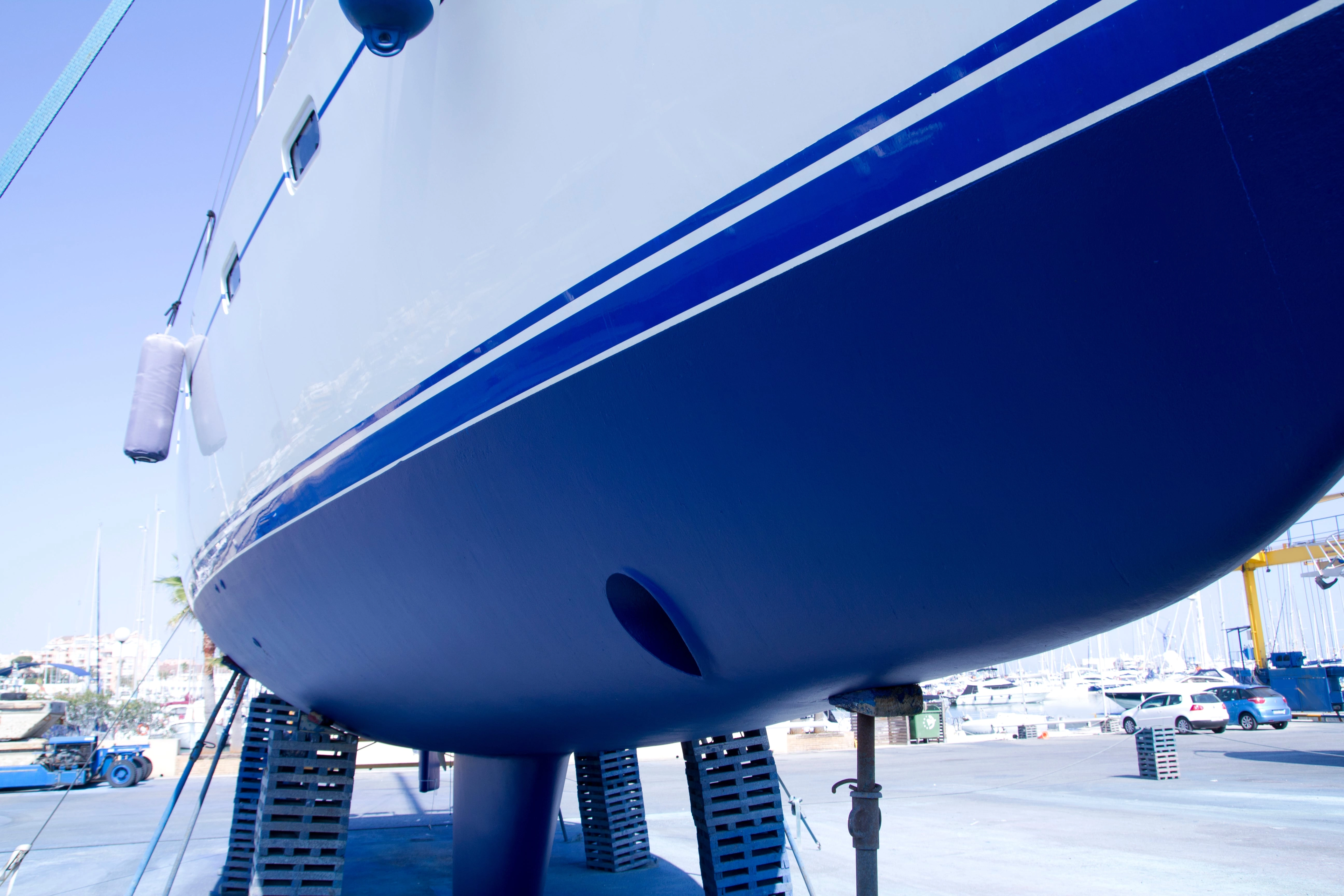
Inverter chargers are great, they combine the power of a battery charger and an inverter into one unit. On installations such as boats or vans this can save valuable space but they offer a few other benefits above having the charger and inverter separate as well.
- Less cabling – Inverter chargers use the same cabling from your batteries for both the inverting and charging side so there is less cabling running to your batteries keeping the installation cleaner and reducing costs on cables.
- Better for your batteries – Inverter chargers use the same cabling for both inverting and charging so when you are hooked up to mains power, your AC loads will run directly from the grid instead of from your batteries which allows them to charge your batteries. This results in a faster charge and less load on your batteries, prolonging their life.
If you are fairly competent with electrics fitting an inverter charger is actually simpler than you may think, you just need to make sure to install certain components to keep everything safe. This is a guide for someone who is looking to fit it themselves, we will explain everything you need, and go over the steps when fitting an inverter charger for someone who is knowledgeable working with electrics but maybe doesn’t know the correct process of fitting an inverter.
Inverter chargers produce 230V which can be highly dangerous if not fitted properly, if you are new to electrics or aren’t very comfortable with what to do we would advise you get an electrician to do your installation.
We will explain the set up an inverter charger system to power some sockets, this allows you to plug in appliances just like you do at home. If you are setting up an off-grid house with multiple ac circuits such as lights and ring main circuits, this is more complicated and would be the job for an electrician.
What you will need
- Inverter/Charger
- AC Consumer unit - (fitted before your sockets on the AC OUT)
- AC socket/ sockets
- AC cabling for AC OUT - (to RCD and socket) – 3 core multi strand AC cable
- AC cabling, for AC IN (either an extension cord with plug and socket or cable to run from your shore power consumer unit) - use multistrand 3 core cable
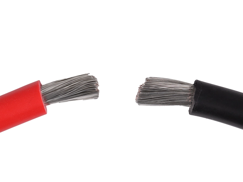
- Single Core DC cable - battery to inverter/charger
- Inline fuse block - on DC cabling to protect your system in case of a short circuit.
- High current On-Off switch (to disconnect the inverter charger from the battery)
- Ring crimps used on the DC cabling
Sides of an Inverter Charger to set up
There are three sides to an inverter charger, you have:
AC INPUT – This is your mains in and will power the charger as well as run your AC loads while you are hooked up to power.
AC OUTPUT – This is the cable/ cables you will run to your 230v loads. In our case through an RCD and into a socket.
DC SIDE – This is the cable running directly to the battery and while you are inverting – power is coming from your batteries and when you are charging the power runs back.
EARTHING – You need to earth the AC output to your common ground, your consumer unit will have an earthing output.
The main point when setting up an inverter charger is ensuring safety precautions are taken, making sure you have consumer units to protect circuits and people in case of a short circuit. Having correctly sized cables, the right size of fuse on the DC side to avoid any fires and an On-Off switch. This way your system is safe.
Wiring the AC INPUT
You can do this first, if you wire a dedicated cable, don’t plug this until the installation is finished, if you are running from your shore power input. Make sure you are not hooked up to power and you have switched the breaker off to make sure no power goes into the system.
As mentioned above there are two options for the ac input, you can wire a cable with a plug on to make it like a charger that would come with a plug. This means you will need an extension cord to plug it in and on a boat or a van this can stop you from closing your hatch or shutting your door properly.
The above is not the best option for a boat or van install if you can, many sites and harbours have 3-pin CEE outlets, therefore if you have a shore power inlet with a consumer unit within your vehicle, hooking the charger up to that means when you arrive you can plug your shore power cable to your internal socket and you have AC power within your vehicle while being able to lock your doors properly.
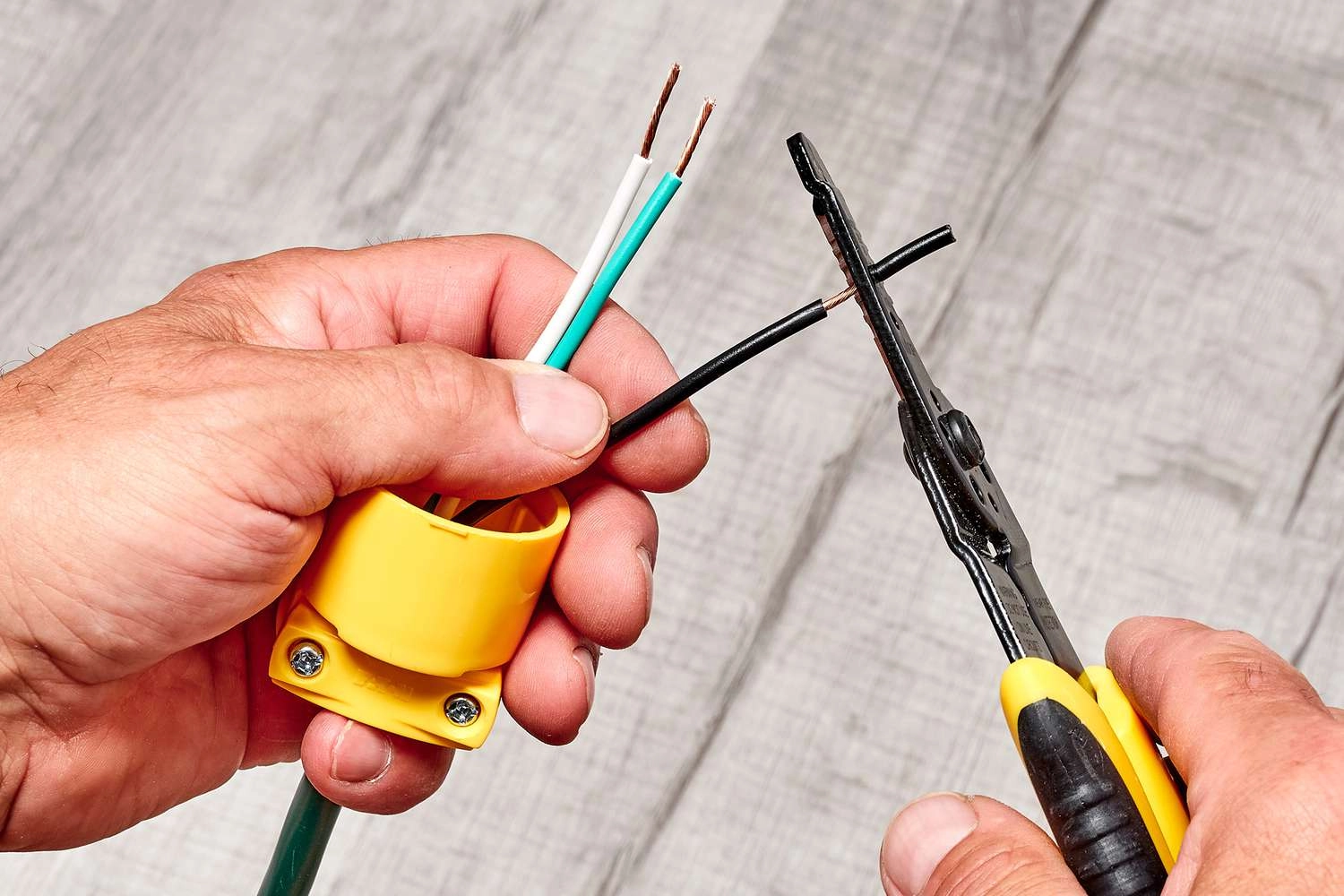
Removing Socket from Extension Cord
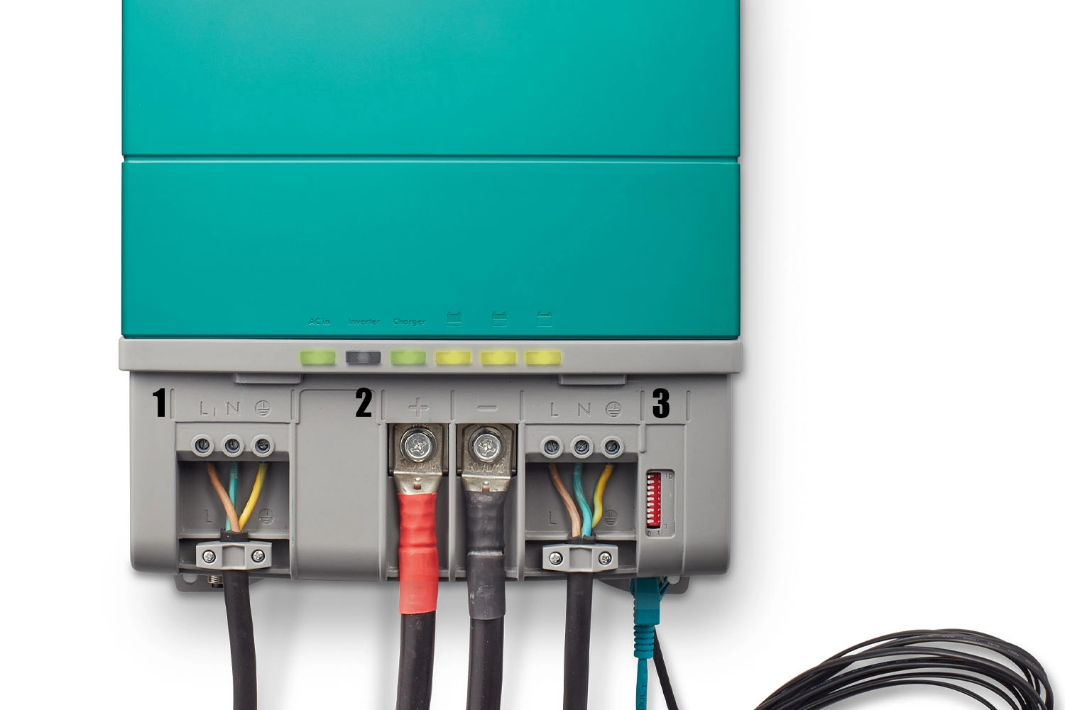
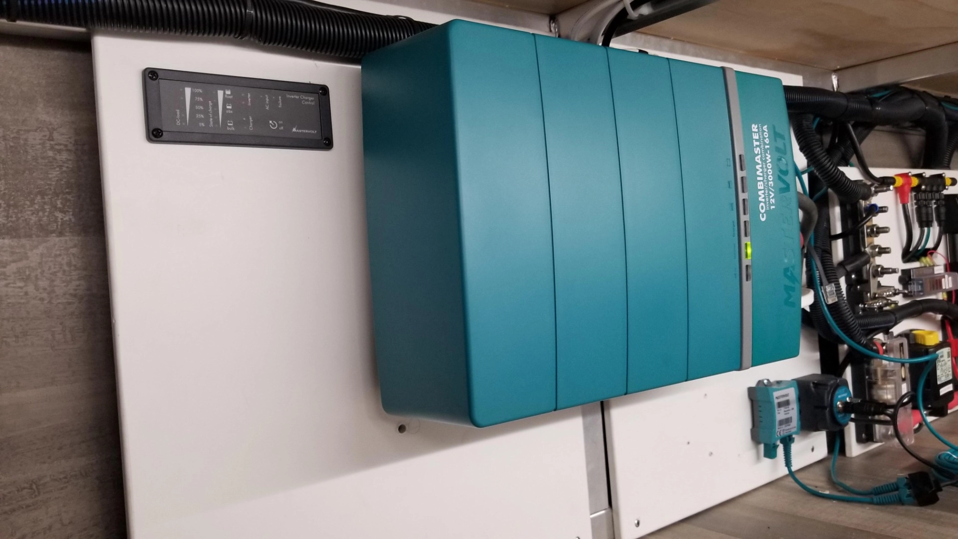
Inverter Charger Wiring 1. AC input, 2. DC cables 3. AC Output
Both methods are similar, if you have shore power, as mentioned above make sure there is no power coming in so that the installation is safe. You will have a Live, Neutral and an Earth, your inverter has corresponding inputs for these on the AC IN section, Strip the outer insulation back just far enough that the 3 internal wires will reach the correct inputs but you won’t see them when the cover goes back on. Then strip the insulation on the inner cables just enough that they fit into the inputs and there won’t be any copper showing. Run this cable to an output not being used on your consumer unit.
If you are going the extension cord route, get your extension cord of the desired length, remove the socket from the end, you may be able to unscrew it but often you need to cut it. Repeat the same process for connecting it to the inverter charger.
WHAT YOU WILL NEED
- Cable crimper – for stripping the insulation off cables
- AC cable for running from shore power consumer unit or Extension cable to cut plug off. (Rated to the max draw of inverter charger)
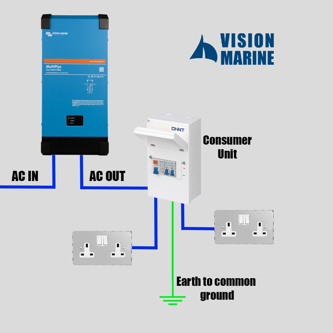
Wiring the AC Out
On the AC side, this is where the consumer unit breaker comes in, this ensures if anything shorts out your system and more importantly lives are safe. Similar to the AC IN you connect the 3 internal wires on the AC cabling to the corresponding outputs on the Inverter charger ensuring no copper or internal wires are visible. Run this cable to your consumer unit, somewhere that is accessible and isn’t too far away from your grounding point if possible so that you can run the earth wire easier.
A grounding point can vary depending on your boat or van but generally it is the engine block on a boat which is connected to your anodes or on a van it is usually the chassis. AC and DC grounds can share the same common ground.
For simpler installation, each socket or larger appliance such as an emersion heater will have it’s own breaker and output on the consumer unit. This saves you from having to set up ring mains. Wire these sockets up from the consumer unit to where you want them.
WHAT YOU WILL NEED
- AC cable – to run to consumer unit then to sockets
- Consumer unit with enough breakers for circuits you want to run
- Plug Sockets
- Cable crimper – for stripping the insulation off cables
- Earthing cable
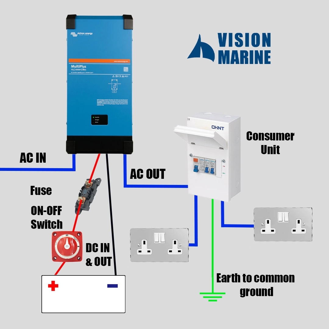
DC Wiring
As an inverter charger is a charger with an inverter in it, the DC cables get treated as a charging cable. This means they should be connected directly to your main battery bank, in between the battery bank and your inverter charger you should fit an inline fuse block on the positive cable. A MEGA or MAXI fuse is a good option if you have appliances with a high inrush current which is higher than the output of the inverter as these have a delay which stops them from blowing with inrush currents. A couple of ring crimps will be needed to wire this in.
Just after the battery and before the fuse you should fit a high current On-Off switch, also on your positive cable. This will allow you to disconnect the inverter charger to ensure there is no current on the AC side when you need to do work and to also shut it off to stop it from draining your battery if you are not there and the charger side is not plugged in.
Connect the single core cable to the battery inputs/ outputs on your inverter charger, usually they have bolts coming out so the connection is done via ring crimps.
Keep the distance from your inverter charger to your battery as short as possible as cables are expensive so this keeps costs down, longer cables can also be affected by voltage drop requiring thicker cables further increasing costs.
If you have other charging sources such as a solar charge controller or want to hook up two inverter chargers. You can introduce a positive and negative bus bar to merge all of your incoming charges to your main bank, this keeps cabling simpler and less cluttered as only one cable comes down to the battery on the positive and negative side as opposed to multiple.
The Victron Lynx distributor is a good option for this as it is rated to a high amperage and has both the positive and negative side built into one unit with a cover with each input having it’s own fuse.
WHAT YOU WILL NEED
- DC cabling (rated to enough amps)
- Cable crimper – for stripping the insulation off cables and crimping ring crimps onto cable
- Ring crimps, large enough for the cable to connect to the inverter charger and onto your battery.
- Blade Fuse (rated to enough amps)
- Battery On–Off switch (rated to enough amps for the current that will flow through it)
- Bus bars if you have other charging sources and don’t want over-crowding with cables on your battery.
Sizing your components
Correctly sizing your cables, fuses and switches is important for safety, here is how to size the components of your system.
DC cabling – Usually the cable size that is required will be in the manual, with varying sizes based on the length of cable required. Always check that first and go with the recommended sizing but if you can’t find it.
Divide the rated wattage by your battery voltage to get amps, add 20% to this value by multiplying it by 1.2, then find a cable rated to this amp range. (You may need to round up to a round number)
Put this into cable sizing and the amps you are running through a cable voltage drop calculator to make sure it is fine for your length.
AC cabling IN – a lot of inverters state their max input current, make sure whatever 3-core flexible cable you are using is rated to a higher amount than this.
AC cabling out – The AC cabling coming out can often be higher than what comes in as when hooked up to the grid while not charging they can use the inverter to boost the output. This information will be in the manual.
Fuse for DC cable – Size this to the rating of the cable if you can, in a short circuit the amps will jump up super high which can damage the equipment but melt the cable as well and can potentially cause a fire. We want the fuse to blow first breaking the circuit. We also don’t want it to blow when we reach max power so keep the fuse size around the max cable amperage or as close to and you will be fine.
If you are running a fridge, power tools or appliances that can have a high inrush current higher than the max output of your inverter, a MEGA or MAXI fuse is a good choice as these have a longer delay meaning they won’t blow from the very brief high current.
SAFETY
If you plan to install the inverter charger yourself, which you can see on a boat is not too complicated, with anything 230V we highly recommend getting an electrician or marine electrician to test and commission your system. This will be far less expensive than a full install, but will ensure everything has been done safely.
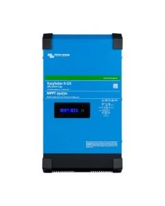
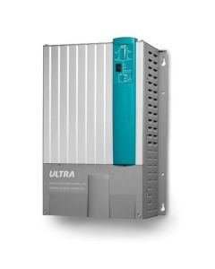
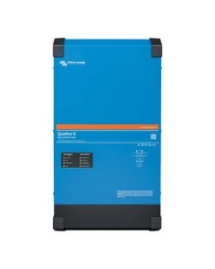
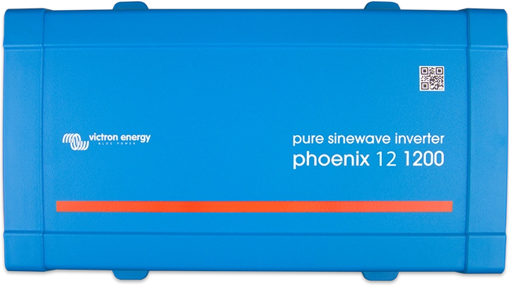
Now you've had a look at what's involved in the fitting here are some of the inverter chargers we offer, we have one of the best-sorted categories so when you click on a product you will have different power options to choose from.
-
-
-
-
-
-
-
-
 Victron MultiPlus Inverter/Charger 24V (New Style)As low as £331.46
 -
-
 Victron MultiPlus Inverter/Charger 48V (New Style)As low as £308.84
 -
-
-
-
-
-
-
 Victron MultiPlus Inverter/Charger 12V (New Style)As low as £340.71