Setting Up An Inverter Guide
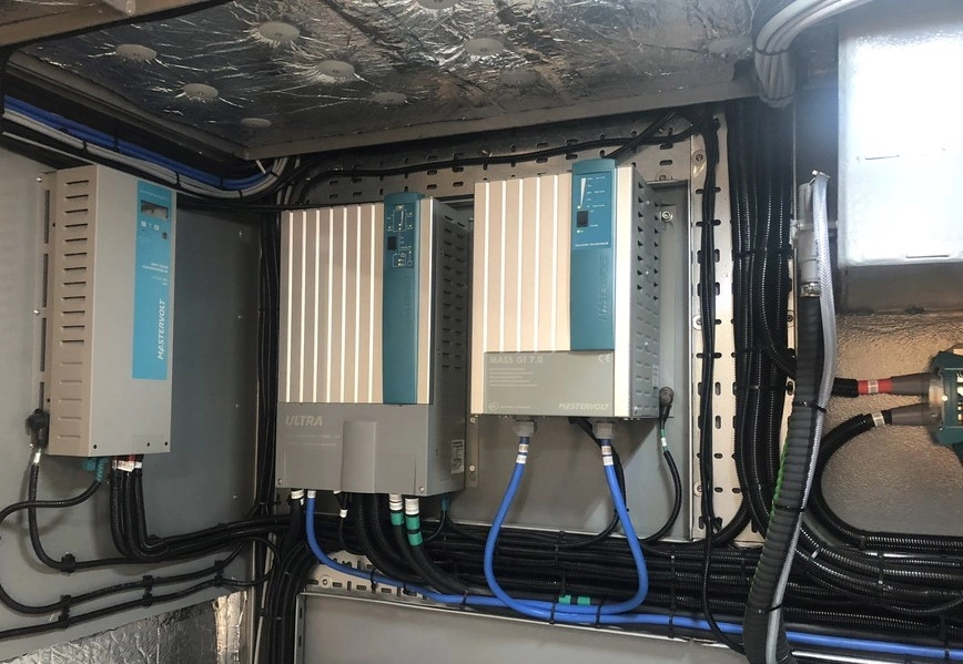
Installing an inverter on your boat or van is great, it allows you to run certain appliances such as water heaters, toasters, fridges and other household appliances while you’re not hooked up to shore power. This brings more freedom to your adventures as you are not missing out on toast, hot water or logging onto your work laptop when stopping at that pretty anchorage or pitch without outlets.
If you are fairly competent with electrics fitting an inverter is actually simpler than you may think, you just need to make sure to install certain components to keep everything safe. This is a guide for someone who is looking to fit it themselves, we will explain everything you need, and go over the steps when fitting an inverter for someone who is knowledgeable working with electrics but maybe doesn’t know the process of fitting an inverter.
Inverters produce 230V which can be highly dangerous if not fitted properly, if you are new to electrics or aren’t very comfortable with what to do we would advise you to get an electrician to do your installation.
We will explain the setup of an inverter system to power some sockets, this allows you to plug in appliances just like you do at home. If you are setting up a larger system or off-grid house with multiple ac circuits such as lights and ring main circuits, this is more complicated and would be the job for an electrician.
Some inverters have the AC output socket built in, these will have an internal RCD and mean you can plug in a multi-socket extension cord directly, with one of these you only need to set up the DC INPUT side. Other inverters don’t have a socket but have a built-in RCD switch, this saves you from having to fit a consumer unit but still requires wiring on the AC side while larger inverters need you to set up both the DC IN and AC OUT in full.
Sides to an inverter
- DC Input – Power pulled from your battery bank
- AC Output – Power running to your 230v appliances
WHAT YOU WILL NEED
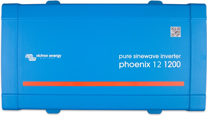
- Inverter
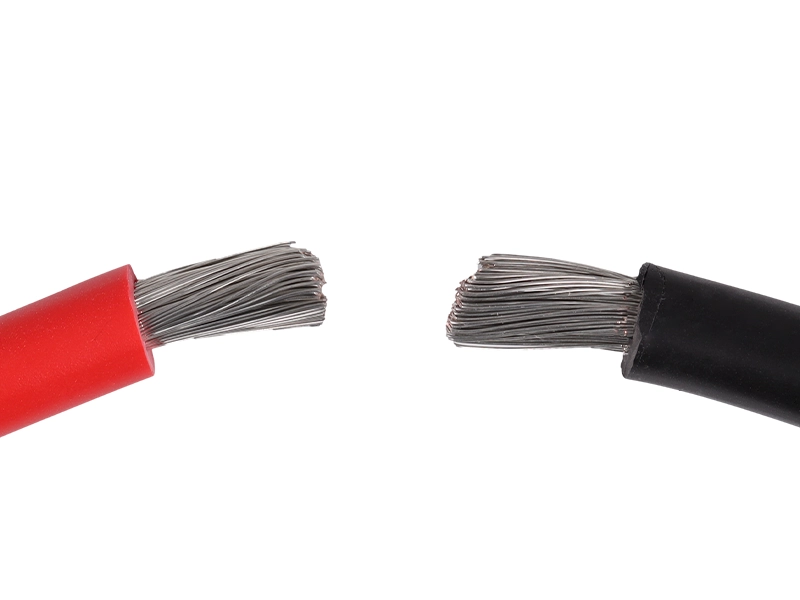
- Single core DC cable (rated to recommended size)
- In-Line Fuse (recommended size for inverter)
- 3 Core AC cabling (not required when the socket is built-in)
- Consumer unit (not required for an inverter with Socket or RCD built-in)
- Ring Crimps
- High current On-OFF switch
Wiring the AC Output
Always fit this first as inverters don’t usually have an on-off button so it will ensure there is no current on the 230V side while you work.
NO RCD BUILT-IN
When there is no RCD breaker built into the unit, cabling needs to run to a consumer unit, this adds a level of safety with RCDs and breakers just like your house has, the outputs from this then run to your sockets.
Your inverter will have an AC OUT section with Live, Neutral & Earth ports. Get some 3-core multi-strand AC cable rated higher than the max amp output of your inverter, strip the outer insulation back far enough that the 3 internal wires can reach the 3 individual inputs but you won’t see any of the internal wires when the cover goes on. The three internal wires should be stripped back just enough to fit into the inputs and wire these to live, neutral and earth.
Next wire the other end up of this cable to the input on the consumer unit, or ease of installation if each output on the consumer unit runs to a separate socket or larger individual appliance such as an emersion heater no ring mains need set up.
Earthing – The consumer unit will have an earth bar or earth output, run an earthing cable from this to your common ground. This can vary depending on your set up but usually on a boat, it is your engine block which is connected to your anodes, on a van it is usually your chassis. (DC & AC grounds can go to the same ground.

RCD BUILT-IN
Some inverters have the RCD breaker switch built into the side of the inverter, in this case you would just need to run the AC OUTPUT to ac distribution panel consisting of breakers, these will protect your appliances or a single breaker if you just want one socket.
Apart from not running into a consumer unit and earthing out of the consumer unit, the set up pretty much the same, usually these inverters have an earthing point built into the inverter so you would run your earth from the built-in earth point to your common ground.
Wiring the DC Input
The DC input side consists of wiring single-core cables from your battery Neg and Pos to your inverter Neg and Pos, your inverter will have large battery inputs, you may need ring crimps to hook them up.
Due to the large current, the inverter gets connected directly to your battery, running in between your inverter and battery fit an inline fuse block on your positive cable, MEGA or MAXI fuses are good if you are running appliances with surge currents as they have a delay and won’t blow. If you don’t plan to run anything with an inrush current an ANL fuse will also do. You will need ring crimps to connect to your fuse holder block.
In between the fuse and your battery bank, fit an On-Off switch rated to a higher amperage than the inverter will draw from your battery bank. This will allow you to turn the inverter off, to ensure there is no current on the ac side if you need to work on it and so you can turn your inverter off when you are not there so it doesn’t drain the battery if you leave accidently something on. Make sure the switch is off and connect this to your battery then your inverter is set up.

Sizing cables and components
Correctly sizing your cables, fuses and switches is important for safety, here is how to size the components of your system.
DC cable
The required battery cable sizing for your inverter can be found in the manual, they usually give this for different distances from the battery as you can experience voltage drop when cable lengths are longer requiring larger cables. The main objective is to have the inverter as close to the battery as possible, this means you can go for the smallest cable possible reducing your costs.
If nothing is stated in the manual, but you can find the efficacy of the inverter, we can size the cable from the draw of the inverter. First divide the wattage by the voltage. Take the efficacy away from 100 to get a remainder, for example, it may be 89% which gives us 11, add this to 100 and turn it into a decimal by dividing by 100. We get 1.11. We can multiply this by our amperage to see what the inverter will pull through the cable. As a safety net, add on 15% to this by multiplying by 1.15 and this will give us an amp rating which is higher than the inverter will pull so we won’t be pushing the cable. It sounds complicated but here is an example, follow this with your numbers.
Our 2000W inverter is running from our 12v batteries with an efficiency of 87% when at full power.
2000 ÷ 12 = 166A – this is the amps our inverter uses to make 2000W (not including efficiency)
100-89% = 12
100+12=112 ÷ 100 = 1.12
166A x 1.12 = 185.92A – this is the actual amps our inverter will pull from the battery
185.92A x 1.15 = 213.8A – this is the amp rating with a safety net,
There won’t be a cable with an amp rating of 213A so we can round it up or down and find a cable with an amp rating of 200A to 240/250A. Google this and you may find an option pop up, if not get a cable brand such as Oceanflex or Ancor and find their single-core cables. In our case the Oceanflex 35mm2 cable does 240A so that is perfect.
If your install is over 5m away from your battery bank, check the cable size you have calculated won’t have too much voltage drop. Put it through a voltage drop calculator with your size, amps & cable. If it says there is too much voltage drop you will need to go a size larger, or try and get the inverter closer to the battery.
Inline Fuse for DC cable
Size this to the rating of the cable if you can, in a short circuit the amps will jump up super high which can damage the equipment but melt the cable as well and can cause a fire. We want this to blow first breaking the circuit. We also don’t want it to blow when we reach max power. Keep the fuse size around the cable amperage or as close to and you will be fine.
If you are running a fridge, power tools or appliances that can have a high inrush current higher than the max output of your inverter, a MEGA or MAXI fuse is a good choice as these have a longer delay meaning they won’t blow from the very brief high current.
AC Cabling
Get yourself flexible multi-strand AC cabling, this just needs to be able to handle the amount of amps that will be running through it. To find the amps your inverter is outputting divide the wattage by the mains voltage. 2000w ÷ 230V = 8.69A = 9A. Some 1.25 or 1.5mm2 cable will be fine.
SAFETY
If you plan to install the inverter yourself, which you can see on a boat is not too complicated, with anything 230V we highly recommend getting an electrician or marine electrician to test and commission your system. This will be far less expensive than a full install, but will ensure everything has been done safely.